Viewing Orthogonal Multi-Planar Reformats
Advanced Visualization allows you to view advanced multi-planar reformats (MPR) of selected image data. Generating an MPR reformat displays orthogonal sagittal, coronal, and axial views from the original image data. The result is either a 2 x 2 or 3 x 1 view set (that occupies the entire screen) with a Result view and three Orthogonal views.
The three orthogonal views are positioned in viewports around or to the left of the Result view, depending on whether you have selected a 2 x 2 or 3 x 1 view set. You access the Advanced Visualization toolbar in the Result view.
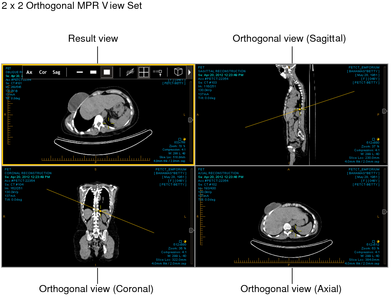
The reference lines in the three Orthogonal views indicate the location of the image in the Result view.
In the Result view, you can reformat views of the series along any plane, not just those orthogonal to the original data. The slice plane location and angle can be manipulated visually, producing oblique and double-oblique views.
The MPR views function as a set, as though they were one viewport, rather than four individual viewports. When you move the MPR view set to another screen, for example, all four viewports move together. As well, dragging and dropping a thumbnail into an MPR viewport results in a new 2 x 2 or 3 x 1 MPR view set. That is, you cannot replace one Orthogonal view or the Result view without impacting the other MPR views.
If you have multiple monitors, you can view multiple MPR views at the same time. You may find this useful if, for example, you would like to view a prior in one MPR view and the current study in another, or an abdomen CT before contrast in one MPR view and another abdomen CT after contrast in another.
If, while in MPR mode, you drag another reformattable series from the Thumbnail strip into the viewport, that series automatically enters MPR mode, and replaces the current series. If you exit MPR mode at that point, however, you will be returned to the first series.
To view an orthogonal MPR reformat:
- Open the MR or CT series that you would like to use to view MPR reformats.
- Click the triangle icon
 to
expand the Advanced Visualization toolbar.
to
expand the Advanced Visualization toolbar. -
Click the arrow beside the Switch to MPR mode button
 to
select either the 2 x 2 or 3 x 1 viewport layout.
to
select either the 2 x 2 or 3 x 1 viewport layout.Three Orthogonal views appear in the viewports, along with the Result view. The 3D cursor and the Oblique tool are activated automatically.
-
To locate a particular point in 3D space on the multi-planar images, use the 3D cursor.
In MPR mode, you move the 3D cursor by clicking and holding the right mouse button. The 3D cursor does not disappear when you release the mouse button. See Using the 3D Cursor.
-
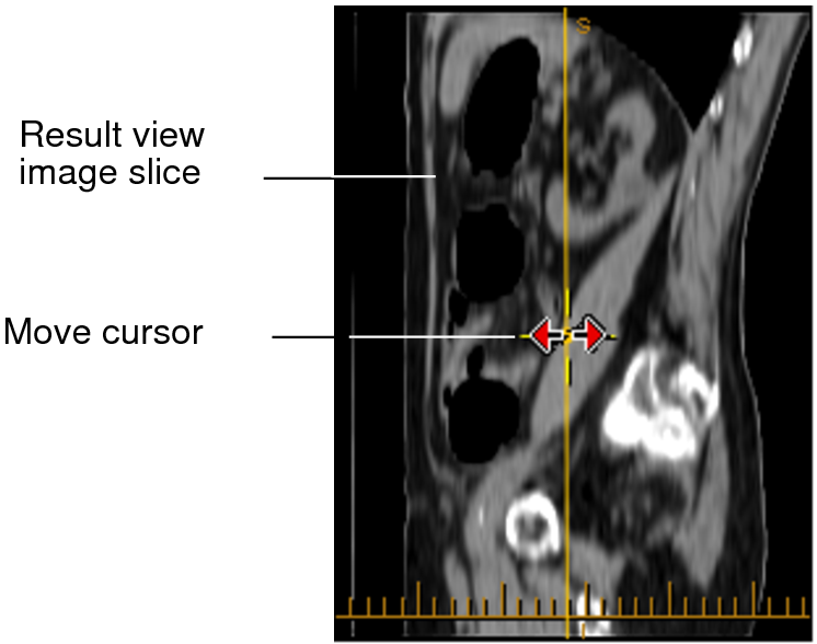
To change the slice location, select an Orthogonal view and place your cursor over the 3D cursor.
The Move cursor appears as a red double-arrow.

-
Click and drag the Slice Plane tool (yellow line) to the new position.
The Result view updates to reflect your changes.
-
To change the slice orientation (create an oblique MPR), do one of the following:
Step
Description
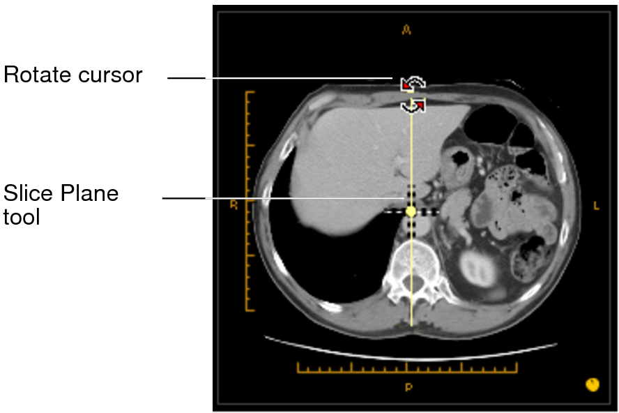
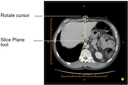
Use the Oblique tool.
Select an Orthogonal view and place the cursor over the Slice Plane tool.
The rotate cursor appears. Click and drag to change the slice orientation. The Result view updates to reflect your changes.
- To create a double-oblique MPR, repeat the previous step on a second Orthogonal view.
-
To change the slice thickness, see Configuring Slice Thickness.
You cannot change the slice thickness of a 3D rendering.
- To change the view of the image in the Result view (to axial, sagittal, or coronal), see Changing Views.
-
To see an expanded version of the Result view image or one of the Orthogonal view images, double-click the image. The image appears in a single viewport. Double-clicking again returns you to 2 x 2 or 3 x 1 layout.
If you drag a non-reformattable series over the MPR view set—when it is either expanded or in 2 x 2 or 3 x 1 layout—you will exit MPR mode.